comme un Professionnel, un Architecte… et Ergonome!")


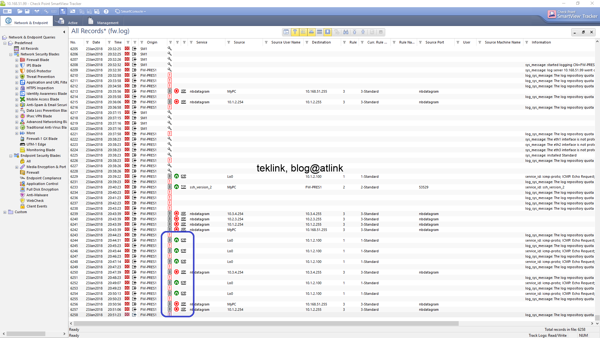
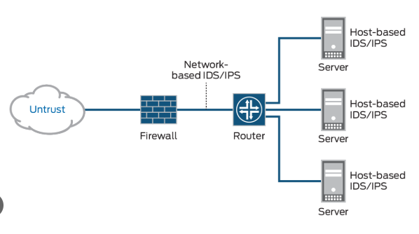
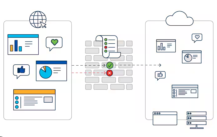
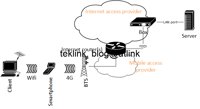
In this blog, we will setup a Checkpoint lab using virtualbox and gns3 on windows. Introduction In this lab we implement a basic security architecture to demonstrate the operation of a firewall cluster to protect our network. Our “security domain” is segmented into four zones: management: only for management, operation and control purposes of equipments…
Setup A Checkpoint Lab Using VirtualBox And GNS3 On Windows