In this post, we explore the operation of Cisco FabricPath (FP) and more specifically Vlan information propagation in this fabric in comparison with other platforms: Catalyst for example from the same vendor. The case is to learn how the switches that are part of the LAN network learn about and support Vlan operation: is there any information exchange in between them? how Vlan is setup? locally on every switch? or globally, centrally, etc.?
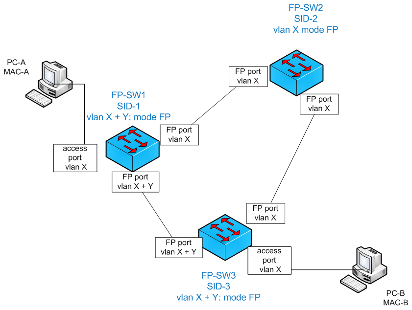
introduce lab setup
PC-A and PC-B belong to the same broadcast domain that is defined by vlan X: means that if i send a Layer 2 brodcast frame it will reach all nodes, hosts belonging to the same brodcast domain that is the same Vlan. Without FabricPath (FP), in a classic packet switch network (LAN), a frame (Layer 2 format of packet per the OSI network model surch as Ethernet) that is sent by PC-A is received by FP-SW1. PC-1 MAC source address is learnt by FP-SW1 in CAM (which is a database that records source MAC addresses against local receiving port of the switch among other attributes: Vlan ID, etc.) to ease further frame local forwarding decisions especially when a reply is received: there’s no need to flood the traffic over all ports but only to the port matching the destination MAC address already copied into CAM (Content-Addressable Memory).
As said before, initially PC-1 did not know about PC-B MAC address (the destination MAC address that it tries to reach) and floods PC-A frame to FP-SW2 and FP-SW3 (on all connected, UP and activated ports). Similarly FP-SW2 and FP-SW3 learns PC-A MAC source address and flood it over all vlan ports except the on the port the frame was received on (using information from CAM that shows this MAC already attached to a receiving port (the source port of arrival)).
The problem here is that FP-SW2 and FP-SW3 re-learn this MAC address a second time from each other. This new entry updates the old one that was pointing to FP-SW1 and this update is treated as an exceptoin thus at CPU level (process switched). Imagine a huge amount of traffic from PC-A, this would result in inefficient switching and network congestion among other problems pertaining to system resources RAM and CPU consumption.
STP
A spanning-tree like protocol (STP) is necessary to avoid such a situation. Spanning-tree protocol builds a loop-free tree by allowing designated and root ports to forward traffic and disallowing the non-designated ones. In the previous scenario, STP would prevent FP-SW2 and FP-SW3 send traffic back if FP-SW1 is the root bridge (the root of the STP root).
This solves the previous problems but burden the network capacity as in this tree PC-A communicate with PC-B over exactly one path at a time: PC-A_FP-SW1_FP-SW3_PC-B. The other path PC-A_FP-SW1_FP-SW2_ FP-SW3_PC-B is unusable being blocked by spanning-tree. To prevent loops, stabilize equipment system (RAM, CPU consumption, etc.), we’ve limited the capacity of our network by half! we can overcome this situation by setting into place many strategies : STP per Vlan such as to split traffic based on Vlan information, use of LACP (as an example) to aggregate physical links (no need for STP) in one single physical link, etc.
FP motivation and operation
Here FabricPath (FP) comes into play. FP processes a multipath loop-free tree for PC-A and PC-B to communicate. When FP is enabled, the switches establish IS-IS L2 adjacencies to each other and exchange topological information. The result of this is that each FP-SW1 is now aware of 2 paths that lead to FP-SW3 for PC-A to reach PC-B. This operation is very similar to routing operation using IS-IS at L3 level.
Only FP-SW1 and FP-SW3 learn PC-A and PC-B corresponding MAC addresses. FP-SW2 that is a core switch in this case, does not learn these MAC addresses that are not attached to it. The network is by design split into two parts : edge that has the knowledge of local hosts that need to connect, and the core that is more focused on connecting edge routers and share their “sources” and “destination” information.
How FP-SW1 dertermines the path to PC-B that is behind FP-SW3?
FP-SW1 receives an FP frame from FP-SW3 with an outer source address field that contains FP-SW3 switch ID (SID) and in the payload, the original Ethernet frame which hints on the source MAC address of PC-B. To reach PC-B MAC address, FP-SW1 builds an FP frame (Ethertype:0x8903) destined to FP-SW3 based on the already learnt information that matches FP-SW3 SID (FP attribute) to PC-B MAC address (Classical Ethernet (CE) attribute). Forwarding of this frame in the FabricPath is based solely on the SID.
FP topological trees
In FP domain, broadcast, multicast or unknown unicast traffic is not handled the same way as unicast known destination MAC address traffic. Similarily to spanning-tree, topologicial trees (identified by FTAG and assigned by ingress FP switch) for this trafic are built by electing roots and identifying least cost path to these roots from FP nodes. The number of these trees is platform dependent and used for load-balancing.
An important fact about Multicast tree in FP and an intelligent new way to check vlan consistency in FP domain
Multicast trees in an FP domain are per-vlan. If a vlan is not configured in a switch, this switch is not part of the corresponding tree and is pruned from the corresponding vlan tree.
Is it possible from any switch to identify the switches that are participating (not pruned) in a per-vlan topology? Is this view consistent over all FP domain nodes? Yes, group memberships are learnt from igmp at switches (with CE, Classical Ethernet links) using IS-IS by means of GM-LSPs and could be checked in this way:
- On any FP switch check that the required list of vlans are added to the FP topology : show fabricpath topology vlan
- Check the FP multicast routing table that hints on the received group memberships per vlan and the corresponding FP switch-ids
- Use eventually “show fabricpath isis hostname/switch-id” to match switches’ hostnames to switch-ids.
- If vlan is present but some switch-ids are missing. Then check if that vlan is configured on these switches.
As a conclusion
Thanks to this basic information, basic understanding of how FP Multicast topological trees (identified by FTAG) are built in FP using IGMP, IS-IS L2 and GM-LSP, it is easy to check Vlan consistency of the network (sometimes of a huge number or switches) from only one location… this is more intelligent to do this check from only one location than to do it on every node (switch) of the network such as in classical switching networks (Catalyst switched networks) especially where the number of nodes is huge.
On another side, this technological improvement brings new way of doing switching that is more similar to routing (and vice versa). People lacking this knowledge may rush in doing things (troubleshooting, operation, configuration, etc.) in the old inefficient way, losing much more time and energy…


