Home / Network / Multicast routing: a step by step… Part 1

Multicast routing: a step by step… Part 1

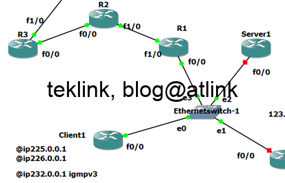
In this post we review a basic multicast routing operation, step by step using output from routers console and traffic packet capture (using wireshark).

In the above test lab, Servers send multicast trafic to both clients: client1 and 2.

In IPv4, multicasting servers use class D range of addresses: 224.0.0.0-239.255.255.255. Some addresses are well known and others are for specific use…

In our example, Server2 sends trafic (ping) to group ip @ 226.0.0.1. There’s no need on a cisco router to configure multicast routing on a router to send a packet to a mcast destination. It sends the traffic through the all configured ip address interfaces… as shown in the next figure that represent the output of a router console after activating debug.

To see the packets being sent by the server, we disable cef (so that the packets are cpu processed) on the ip enabled interfaces (Fastethernet0/0 and loopback0) and activate a debug ip packets, so packet are switch processed…

Server1 sends trafic to destination 226.0.0.1 using local interface addresses: 1.1.1.1 and 123.1.1.254

IP @226.0.0.1 represents a group of receivers… all receivers that have subscribed to this channel! This is an optimization in comparison with unicast trafic. In the case of unicast, one flow of the same trafic would be needed for each receiver. For each flow the server maintains a different per receiver session which not efficient. Using multicast only one flow is sent to the bench of receivers… allowing efficient bandwith usage and system ressource optimisation of the network.

In our example, Client1 (a cisco router) starts accepting and processing trafic to 225.0.0.1 (Server1) destination as soon as IGMP is enabled on the receiving interface and joined the group

Because Client1 and Server1 are located in the same subnet, Client1 responds to Server1 pings to ip @225.0.0.1.

In Wireshark capture, Server1 uses the mac @01:00:5e:00:00:01 (in wireshark) but should’ve used the Ethernet MAC address range 01:00:5e:00:00:00–01:00:5e:7f:ff:ff (with an OUI owned by the IANA).

This range has 23 bits of available address space. The first octet (01) includes the broadcast/multicast bit. The lower 23 bits of the 28-bit multicast IP address are mapped into the 23 bits of available Ethernet address space.

If two hosts on the same subnet each subscribe to a different multicast group whose address differs only in the first 5 bits, Ethernet packets for both multicast groups will be delivered to both hosts, requiring the network software in the hosts to discard the unrequired packets.

Server2 is not on the same subnet: routing is needed.

By definition each router interface is a broadcast domain and the same broacast (multicast) could not natively cross router interfaces…

Server2 sends multicast trafic to ip @226.0.0.1

R1 should accept this trafic and forward it down to Client1

Using debug ip packets and deactivating ip cef on the interface facing the Server2 we check that R1 receives server flow

The mroute (mutlicasting routing) table indicates the multicast forwarding is not activated

To accept (and process) multicast trafic (from outside the router) we should enable PIM protocol on the interface on which the server trafic is received

PIM is enabled on the interface facing the server in dense mode

We check that the source is added to the mroute table

The mroute table entry (S,G) indicates the source and multicast group address. It indicates also the incoming interface and that the RPF neighbor is the router itself. Notice that the outgoing interface list is NULL which means that the router has no idea on where to forward the received packets.

The (Source, Group) or (S,G) entry is flagged as PT: Pruned and SPT-bit set to indicate that the flow flows over the shortest path tree from the source (server) to the destination (receivers)

The router accepts the flow from the server. To fowarded it to the subnet where our clients (receivers) reside, we add a static membership on R1. This static membership is an alternative to clients joining dynamically (using IGMP) the group at R1.

A capture in clients subnet shows that the multicast forwarded by R1 is received

Client1 could’ve indicated its willingness to receive Server2 multicast to router R1, using IGMP, so there’s no need to configure R1 statically

For ping to succeed, a routing back from the client to the server is needed…

We check that server receives replies from the the client

We check also that the client has active memeberships and on which interface

In R1 we get more details on forwarding mcast trafic in the mfib table

We check that the router is no more configured with a static igmp entry (that represnts all the clients on subnet 123.1.1.0/24)

We check that the (*,G) is present and indicates the correct incoming and outgoing interfaces.

Using IGMP, R1 fill in with the correct information the outgoing interface list that points to “Reporter” 123.1.1.1 which is our Client1…

To be continued…

Leave a Reply

  • Transmit Power Control in IEEE 802.11 Cisco WLAN networks
    TPC stands for Transmit Power Control. It’s a one of Cisco RRM, Radio Resources Management, techniques that are aimed at tackling interference, cross and co-channel, in Wlan networks. RRM: TPC, CHD and DCA It works tightly with CHD, Covergate Hole Detection, to optimize transmit power. TPC tends to minimize the transmit power and CHD to eliminate
  • 10 security measures against 10 attacks in a LAN network – Part I
    An Ethernet switch is the central element of a LAN network and operates at data link OSI layer. Every switch port defines a collision domain and can extend a broadcast or broadcast frame domain that is stopped by a router routed interface that operates at network OSI layer. By default switches support one broadcast domain
  • Understand how Aruba ARMizes your WLAN for sure!
    Presenting ARM In this post, that is a part of a serie of post that discuss how Wlan to radio ressources management, we talk of Aruba way of doing it. The figure shows a simple wlan network of 6 AP or access points. This is heatmap showing that radio signal is very strong (in red)
  • Understand RIP Routing Timers All in One Shot!
    This post is part of a series of posts about dynamic routing protocols and especially RIP. We’ll try to get a deep understanding of its operation and function as an introductory to dynamic routing logic in general. You’ll see that what we think easy may hide an incrementing complexity… a little introduction Berfore we start
  • DUAL route FSM Processing of EIGRP Queries
    This blog is a part of series of posts about EIGRP routing protocol. Let’s recall that EIGRP is one of the so called IGP routing protocols. IGP stands for interior routing protocols as opposed to EGP or exterior routing protocols. In addition EIGRP is a hybrid as it borrows some similiarities to distance-vector and link-state
July 2025
M T W T F S S
 123456
78910111213
14151617181920
21222324252627
28293031