In this blog, let’s discover the DMVPN feature. DMVPN stands for dynamic multipoint virtual private network and as per its naming, refers to the ability for many routers to share the same network built on a Wan equivalent to being connected to the same Lan.
Before we start
Before we start a little refresh on the DMVPN feature. in two words DMVPN is gre and NHRP.
The use case
How is it possible to connected wan separated routers in ethernet like fashion?
Connect the ethernet to a switch
The simplest way to interconnect 3 or more routers in the same broadcast domain (and the same subnet) is by attaching them to a switch (or hub) in the same vlan.
Connect the ethernet to the isp network
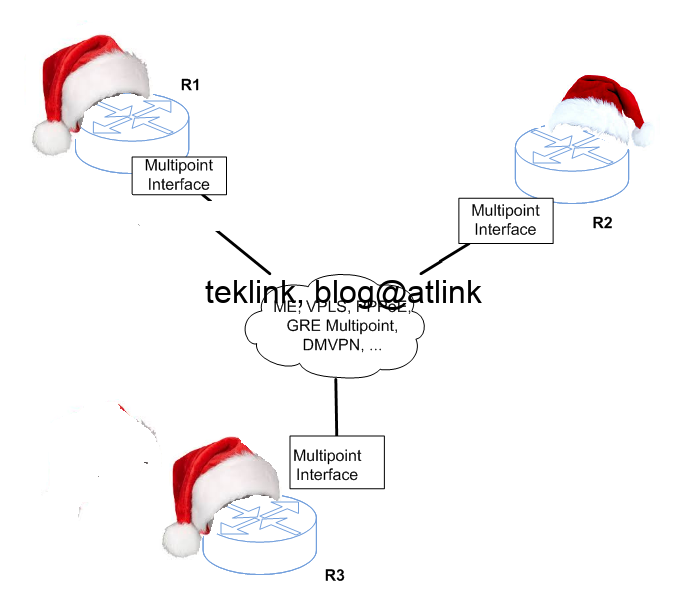
We focus only on routers that are connecting via Ethernet. In case they’re separated by long distances, an ISP may be required to put them together. From a network access perspective, they could be interconnected in ways such as:
- ME
- PPPoE
- DMVPN
- Pseudo-wire in VPLS
How a broadcast is processed
A broadcast, a ping to 100.0.0.255/24 as an example, is not treated the same way among these features.
A broadcast over pppoe
PPPoE runs in a Hub and Spoke fashion. R1, R2 and R3 share the same subnet but a broadcast is sent to only the last directly attached router per the output of Cef or the first attached router per the ip routing table output.
What ip cef says
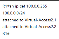
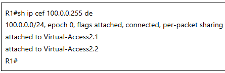
R1#sh ip cef 100.0.0.255
100.0.0.0/24
attached to Virtual-Access2.1
attached to Virtual-Access2.2
R1#
The show ip cef command shows how the destination resolves to an adjacency which hints on the interface the router will used to encode the outgoing packet destined to the destination. In the output the router tell us that to join the 100.0.0.255 host two interfaces are available the virtual-access2.1 and virtual-access2.2 interfaces.
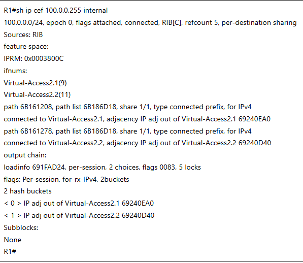
The show ip cef internal commands shows that both paths are successfully resolved to the correct adjacencies.
The internal version of the show ip cef command shows more interesting information to understand how the routing decision is based. The forwarding information indicate that the source of the ip information is the RIB. Next two interfaces or paths are available to handle this traffic. Both interfaces can be used in per-destination sharing. So based on the destination, the output interface to use is calculated.
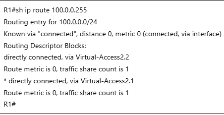
The routing table (RIB) shows that two paths are available for 100.0.0./24 routing but only the directly connected via virtual-access2.1 is used (the presence of the star mark): no multipath.
The ip routing table shows the path that the router will use to send packet destined to 100.0.0.255. The star next to the virtual-access2.1 interface shows that this path is the preferred. The router has to pick only one to full fill this routing task.
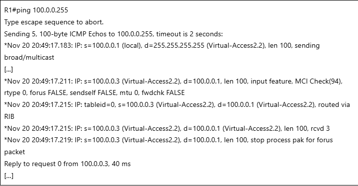
A debug on packet forwarding shows that only one path is used each time…
Change the sharing scheme
The ip cef command showed that the sharing between interfaces is dependent on the destination. So let’s change the sharing algorithm from per-destination to per-packet but with no help:
We check on the same command output that the sharing is per-packet now and not per-destination.
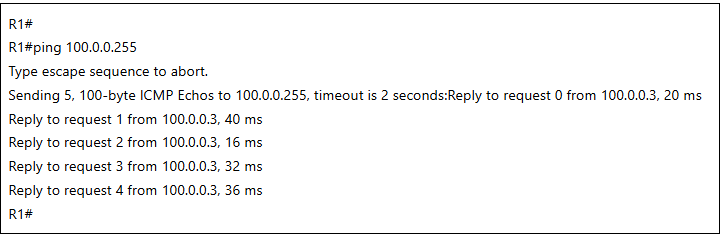
We receive only a reply from one destination. We check that no packet is being received from R2 (with ip address: 100.0.0.2).
Changing the sharing scheme between interfaces to per-packet seems to have no effect on the forwarding decision of packet as only on router responds to our broadcast ping. In the next paragraphs we explore how dmvpn could help with this.
Over dmvpn phase 1 and 2
In the first section, we’ve checked how the router handles brodcast we implementing pppoe circuit. in this section let’s start explore the magic of dmvpn. dmvpn comes in three versions 1, 2 and 3.
Let’s check the forwarding table
With DMVPN, the situation is better as per now:
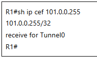
Here the route resolves to a tunnel.
The ping test
We configured dmvpn and in the routing table we check that the route resolved to one path through router new tunnel0 interface.
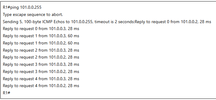
And we check that we receive a ping reply from all routers in the VPN.
Configuring DMVPN phase 2
The good news is that both R2 and R3 routers respond to the broadcast ping from R1.
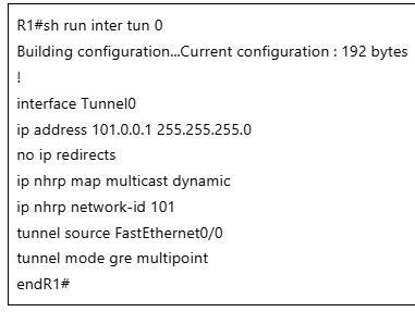
In the configuration we check that the DMVPN is phase 2 that the tunnel mode is GRE multipoint and that the no ip redirects are set.
DMVPN phase 1
Still that with DMPVN Phase 1, only R1 responds to R21:
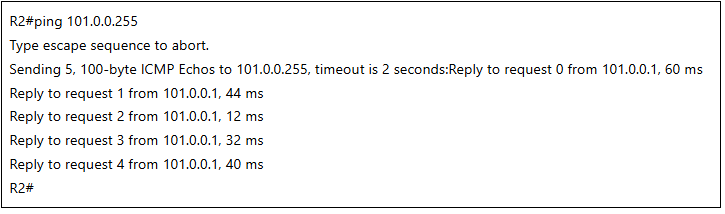
The output shows the result of a ping to the broadcast ip address from R2. only R1 responds to that ping. R2 receives no ping reply from R3.
We check the configuration of the vpn on R2 router. NHRP is configured with an id, the R1 is the server of the mapping, the NHRP node is told to map its multicast trafic to the NBMA address (underlay). Then the GRE tunnel is built with R1. We will notice that in this version, no spoke to spoke tunnels are allowed, that all traffic needs to go through the hub.
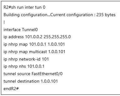
The output shows the configuration for dmvpn phase 1. The configuration is two part: the part that relates to nhrp and the part that concerns the tunnel itself.
Over DMVPN phase 3
The DMVPN phase 3 is an enhancement to versions 1 & 2.
Why using phase 3
With DMVPN Phase 3, two enchancements are added to the first and second phases:
- GRE Multipoint at Spoke which allows Spoke to Spoke tunnels
- And NHRP redirect at Hub that hints Spoke to direct upcoming packets toward target Spoke
- Cef shortcuts at Spoke enables local optimization of Cef operation upon reception of NHRP redirects.
Ping test
Now we could ping the broadcast address from the hub. To obtain the same result from R2 as an example, it is sufficient to add a new NHRP multicast map pointing towards R3:
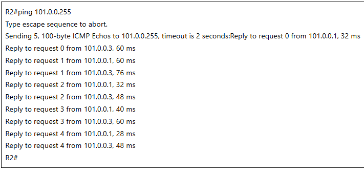
All participants reply to the ping to broadcast.
DMVPN phase 3
We notice the change in configuration to enable DMVPN phase 3 new enhancements : the NHRP shortcut instead of IP redirects at the spoke level to optimize the CEF operation, the redirects at the server level to enable spoke to spoke communications, the GRE multipoint type to enable spoke to spoke direct communications.
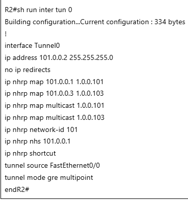
The output shows the configuration for DMVPN phase 3
A wrap up
At the end, DMPVN is very flexible when it comes to the handling of broadcast domains of 3 or more routers in comparison with the classical Ethernet that is by design and PPPoE that is point to point by design, etc. DMVPN looks like an enhanced PPP over Ethernet operation with the advantage of a native Ethernet and it is not limited to Ethernet…
- there’s a need here to ping from the hub also to see ↩︎