Home / Network / Wifi / Transmit Power Control in IEEE 802.11 Cisco WLAN networks

Transmit Power Control in IEEE 802.11 Cisco WLAN networks

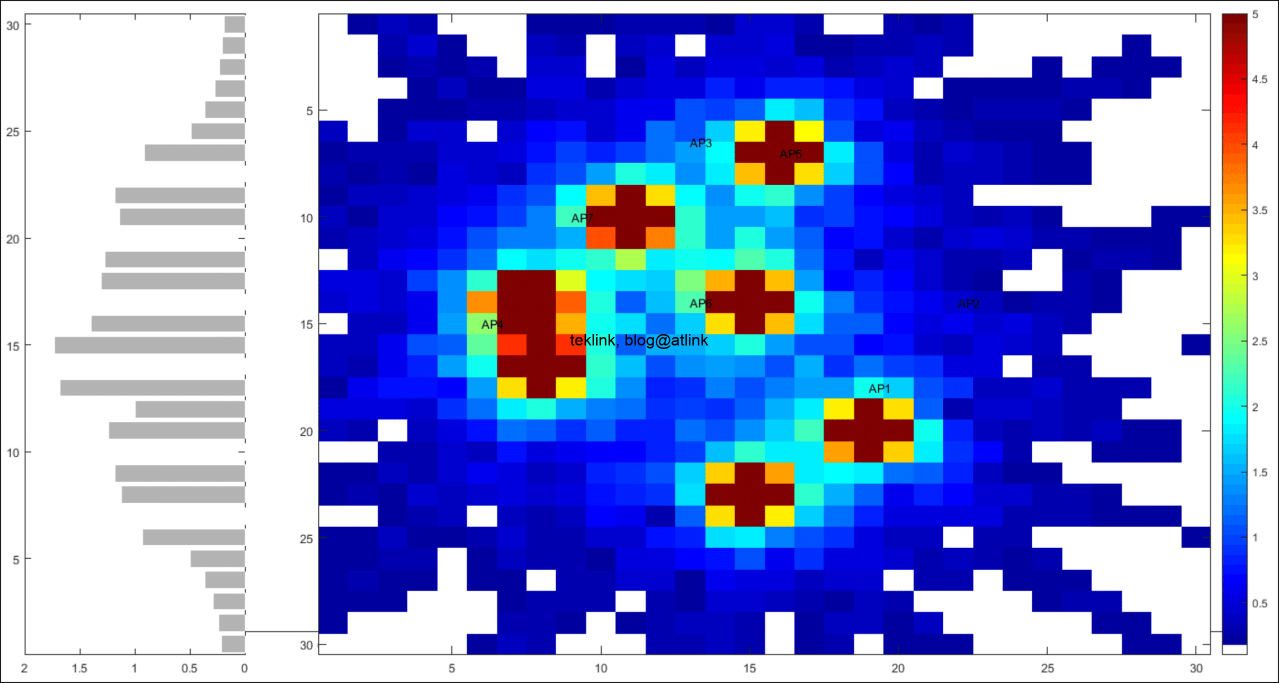
TPC stands for Transmit Power Control. It’s a one of Cisco RRM, Radio Resources Management, techniques that are aimed at tackling interference, cross and co-channel, in Wlan networks.

RRM: TPC, CHD and DCA

It works tightly with CHD, Covergate Hole Detection, to optimize transmit power. TPC tends to minimize the transmit power and CHD to eliminate coverage holes by increasing it.

Transmit Power Control in IEEE 802.11 Cisco WLAN networks

Another difference is that access points (AP) inputs that hints on transmit power to use.  Whereas in the case of CHD, wireless devices (WD) that inform about coverage hole issues.

In a multi-channel condition, TPC works also with DCA, Dynamic Channel assignment. DCA offers a channel diversity and a last resort solution to TPC that couldn’t find an optimized radio resource plan in a single-channel condition.

Cisco TPC comes into play in two flavors depending on design constraints: Coverage Optimal Mode,  TPCv1, or Interference Optimal Mode TPCv2.

Exchanging and processing radio raw data

the radio raw data that is processed by TPC is exchanged by access points in NDP, Node Discovery Protocol, messages.

An NDP message contains this information:

  • Radio identification,
  • Radio group identification,
  • IP address of corresponding controller,
  • Access point channel that serves clients,
  • Information about channel used for NDP purposes,
  • Transmit power level,
  • Antenna type or pattern.

RRM neighbor messages that are exchanged by APs, over the air, are destined at multicast MAC address 01-0B-85-00-00-00 at the lowest rate, at the highest transmit power level, and over all supported channels every 60 seconds time interval, by default.

As an example, in radio “b” these messages are sent at level 1 transmit power and at 1 Mbps rate. In radio “a”, it is sent at the same transmit power level but at 6 Mbps rate instead.

It is to note that this functionality is hard-coded at firmware level of both radios and is untunable by engineer. It is not affected by power level and rates configured for regular radio interface users.

In a controller based architecture, NDP messages over-the-air information is further sent from APs to corresponding controller (WLC, Wireless LAN Controller) via CAPWAP, Control and Provisioning of Wireless Access Points, protocol, over the wired interface.

Next, all controllers forward this information to the RF group leader, which is elected among the RF group controllers, to process this information.

After  processing of this information, the RF group leader returns a new radio transmit power level and frequency assignment plan to the corresponding RF group controllers that apply it to their attached network wide.

In general TPC processes these data:

  • RSSI, reported by WD or AP,
  • RRM Neighbor Messages, or OTA messages (Over the Air), 
  • Data from PHY and MAC on APs radio interfaces other than RRM radio messages,
  • Configured and associated to access points radio profiles parameters such as : min/max transmit power levels, third neighbor transmit power level threshold.

Depending on the implementation it could accept also these types of data :

  • CleanAir, which may be seen a spectrum analyzer added to new generation access points and that dynamically hints on radio interface condition mainly interference.
  • CCX, Cisco Client Extension, for the same purpose as Cleanair but at mobile devices (WD) level.

Some other service related data may influence this algorithm processing. As an example, voice deployments for which Cisco recommend as a general guideline these set of configurations :

  • Minimum signal power -67dbm,
  • SNR, at least 25db,
  • A minimum rate of 11Mbps,
  • A minimum of two neighboring access points at at least -75dbm transmit power level,
  • A minimum of 4 overlapping channels at a minimum of -80dbm transmit power level,
  • A 300 ms maximum of RTT,
  • A maximum of 2% packet loss.

The algorithm in a step-by-step

The algorithm initializes as follows :

  1. Ignore reported channel. It is not mandatory to be on the same radio channel.
  2. Send at maximum supported power level over all supported channels on both radios.

Then, every AP lists neighboring access points reordered by their reported RSSI, Received Signal Strength Indicator, in this way :

  1. Initially an access point reports a maximum of 34 neighbor.
  2. These neighbors should have an RSSI higher than -80dBm to be considered.
  3. Then only a maximum of 24 neighbor is kept per access point at controller level (that have an active CAPWAP association to this access point).
  4. A minimum of 4 valid neighbors that have RSSI higher than -70dBm (by default), is needed to trigger transmit power processing.
  5. A neighbor is removed from this list if no NDP message is received in 1 hour time interval.
  6. It is also removed from the list if its reported RSSI is less than -85dBm.

The algorithm processes at access point level the desired transmit power hysterisis, Tx_Hysterisis_Current,  that equal to the sum of the current transmit power (initially at maximum), Tx_Current, and the variation of power threshold, Tx_Thresh, as it relates to the third neighbor RSSI, RSSI_3rd. If the difference between the processed power and the current one, Tx_Hysterisis_Thresh, is at least 6dBm, then the current power must be reduced by 3 db (by half). We should then wait for 10 minutes before re attempting another calculation. To understand better let’s consider this example:

Tx_Max = 20db,
Tx_Current = Tx_Max= 20db,
Tx_Thresh = -67dbm,
RSSI_3rd = -55dbm,
Tx_Hysterisis_Thresh= 6db,

  1. The first condition that triggers TPC processing is met:

RSSI_3rd = -55dbm > -70dbm

  1. The second condition is also met:

Tx_Hysterisis_Current = Tx_Current + (Tx_Thresh – RSSI_3rd)
= 20 + (-67-(-55)) = 8 > Tx_Hysterisis_Thresh = 6db

  1. We reduce the power by half (3db):

Tx_Current = 17db

  1. After 10 minutes and if:

Tx_Max = 20db,
Tx_Current = 17db,
Tx_Thresh = -67dbm,
RSSI_3rd = -55dbm,
Tx_Hysterisis_Thresh= 6db,

  1. We verify the the fist condition is still met
  2. But this is not the case for the second condition as:

Tx_Hysterisis_Current = Tx_Current + (Tx_Thresh – RSSI_3rd)
= 17 + (-67-(-55)) = 5 < Tx_Hysterisis_Thresh = 6db

  1. Then we keep the current power level:

Tx_Current = 17db.

Further notes 

  • The 4 neighbor minimum number necessary to trigger the algorithm could be explained by the fact that in radio b we could not have more than 3 non overlapping adjacent channels.
  • Transmit power level depends on the chooses channel: in UNII-1 (802.11a channels ranging from 36 to 48) level 1 corresponds to a power of 15dbm, whereas in UNII-2 it is 17dbm and in UNII-3 it is 23dbm.
  • Pinningeffect: the algorithm suffers from lack of possible solutions. This is a frequent design issue !
  • Cascadingeffect: in some situation a simple change at an access point level may impact the whole network stability. This may be related to weaknesses of the algorithm itself with regard to radio modelization and impact estimation on overall radio network ; and to radio interface own property being instable and dynamic by nature.

References

[1] Radio Resource Management under Unified Wireless Networks, Documents ID : 71113, Updated : May 17, 2010, Cisco.
[2] Cisco Wireless Controller Configuration Guide, Release 8.0, Configuring RRM Neighbor Discovery Packets, Cisco.
[3] Cisco Wireless Controller Configuration Guide, Release 8.0, Configuring RF Groups, Cisco.
[4] Configuring RRM (Cisco Wireless LAN Controllers), http://what-when-how.com.
[5] Entreprise Mobility 7.3 Design Guide, Chapter 2 : Cisco Unified Wireless Technology and Architecture, Cisco.
[6] Cisco Wireless Transmit Power Control, http://www.insearchoftech.com.
[7] Radio Resource Management-Radio Frequency Grouping Algorithm, Release 7.4, Cisco.

Tagged:

Leave a Reply

802.11 (4) application (2) architecture (4) asm (4) automatisation (2) cagd (3) chd (2) cisco (6) command (5) controller (1) cost (6) coverage (5) debug (10) distance (6) dtls (2) dynamic rrm (5) firewall (2) fortinet (2) ieee (4) igmp (5) igp (8) interference (2) internet (3) ip (2) logique (2) loop (5) mac (3) machine learning (3) meraki (1) model (2) mpls (3) mroute (4) multicast (5) nat (2) ndp (2) network (3) next-hop (5) nurbs (3) osi (6) pat (2) pim (4) poisoning (6) projet (2) qos (2) radio (5) rib (5) rip (5) route (6) router (6) routing (15) rpf (4) rrm (10) security (3) show (5) simulation (2) sla (2) snr (2) solution (2) split-horizon (5) sql (1) ssl (2) ssm (4) static (6) stp (2) summarization (5) tcp (2) translation (1) travail (2) udp (2) vpn (3) vrf (3) wifi (11) wireshark (2) wlan (7) wlc (5)

  • Book presentation: dRRMize your WIFI… and get your head out of the box!
    In this post we present the work accessible via this link: dRRMize your WIFI… and get your head out of the box!, about radio ressources managmenet in a WLAN entreprise network. RRM or Radio Ressource Management being fundamental to the operation any unified wireless network and a master piece of any WLC (the Wlan controller).
  • vPC vs VSS
    Si l’objectif “historique” est le même : s’affranchir de la limitation de STP (blocage de ports pour prévenir les boucles), de l’usage des FHRP (HSRP, VRRP) pour équilibrer les liens, d’augmenter les performances en débit et capacité de calcul, d’éliminer les SPOF liés à l’utilisation d’un seul châssis ou stack de switches… les implémentations du
  • Présentation de livre: D.A.T(er) comme un professionnel, un Architecte…
    Dans ce blog, je présente ce travail sur le DAT ou Dossier d’architecture technique d’un point de vue d’un architecte réseau et services (sécurité, qualité de service, gestion d’infrastructure). Le lien vers le travail complet est: D.A.T(er) comme un professionnel, un Architecte… Le DAT… Le dossier d’architecture technique ou DAT s’inscrit en amont dans le
  • Book presentation: La dRRM du WiFi… en action!
    Ce blog présente le travail que vous pouvez retrouver sous le lien: La dRRM du WiFi… en action!, concernant la gestion des ressources radio dans un réseau wifi. La gestion des ressrouces radio ou RRM qui est au coeur de tout développement ou conception d’architecture wifi (d’entreprise ou publique). La RRM commen processus ou module
  • From router configuration to Excel… a basic how to automate configuration work process!
    comment récupérer une certaine information d’un fichier de configuration (routeur IOS de Cisco par exemple) et la mettre dans un fichier Excel en vue d’un traitement plus avancé ce traitement peut être simplement de comparer cette information de plusieurs sources (du routeur et du pare-feu, par exemple) à titre d’exemple nous souhaitons vérifier que les
September 2025
M T W T F S S
1234567
891011121314
15161718192021
22232425262728
2930  
Table of Contents
Copied!