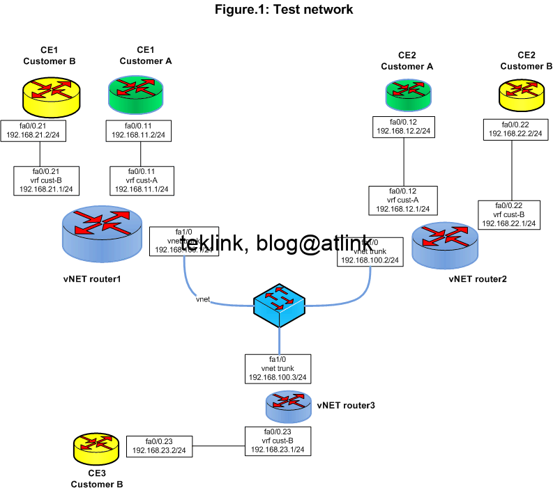
Home / Network / EIGRP over a vNET trunk

EIGRP over a vNET trunk

In this blog we’ll explore the operation of IGP interior routing protocol EIGRP over vNET trunks (another way to say networking trunking similar to vlan trunks used in L2 network by switches to trunks multiple traffics from different vlans into the same physical link)

little introduction

New IOS release 15.x introduced Easy Virtual Network (EVN) functionality to leverage some existing deployment features such as VRF-Lite and QinQ.

Its ease of configuration is a real advantage. The idea is very simple: tag each VRF and trunk them together to other vNET routers (PE).

network setup

We will show an example of how it runs on an EIGRP deployment of CEs (customer edge routers, Customer side) connecting to each other through PEs (provider edge routers, ISP side) that are vNET routers.

In Figure.1, customer A (in green) interconnects two CEs: CE1-A and CE2-A through vNET router1 and router2. Customer B is represented in yellow and interconnects three sites. The configuration of participating routers is given next:

vNET-R1

vNET-R2

vNET-R3

In summary the configuration includes these elements:

  • for each vrf a route distinguisher (local scope) and vnet tag (domain scope) is defined
  • router interfaces are then assigned to corresponding vrfs
  • vnet trunk interfaces are defined
  • under the same eigrp named routing instance routing for vrfs is enabled

A typical configuration file content is given next:


!
vrf definition cust-A
vnet tag 100
rd 1:1
!
interface FastEthernet0/0.11
description to_CE1-A
encapsulation dot1Q 11
vrf forwarding cust-A
ip address 192.168.11.1 255.255.255.0
!
interface FastEthernet1/0
vnet trunk
ip address 192.168.100.1 255.255.255.0
duplex auto
speed auto
!
router eigrp VNET
!
address-family ipv4 unicast vrf cust-A autonomous-system 1
!
topology base
exit-af-topology
network 0.0.0.0
exit-address-family
!
end

Cisco EVN in action

EVN or Cisco Easy Virtual Network introduces the concept of a vNET trunk and behave such as bundle of sub interfaces affected to each corresponding vrf (vpn) with an inherited or local IP configuration

First, each vrf is tagged with a different vNET id that ranges from 2 to 4094. Second, vNET trunks are configured toward other vNET routers that are generally PE routers.

As soon as vNET trunks are configured, sub interfaces are automatically created under vNET trunk physical interface and attached to the corresponding VRFs. In the figure output we check the result of the show vnet command. New sub interfaces were created on the vnet trunk FastEthernet1/0 (in yellow).

By default, these sub interfaces inherit the same IP configuration from the vNET trunk. We understand here why it is not possible to configure a vNET trunk over a sub interface! and it’s quite bizarre to see multiple sub-interfaces (router interfaces) having the same ip address in the output of the show ip interface brief…

We check next on R1 that EIGRP neighborship is established on previously created sub interfaces with the corresponding routers R2 and R3 in our case:

We notice that routing information is exchanged transparently as if it was done in a VRF-Lite mode configuration (each vrf routing table is separate for the other). An example of a learned EIGRP route:

As a conclusion

Ease of configuration is a real advantage of this feature.

In contrast with VRF-Lite, EVN uses the same physical interface to bundle all vNETs. Each VRF is identified to a different vNET tag which is similar to MP-BGP where VRFs are identified by local MPLS labels.

But EVN presents many limitations :

  • Number of VPNs is limited by the number of vNETs
  • Number of vNETs limited by the number of available vlans at the core network or between vNET routers
  • Limited scalability in growing networks in comparison with MP-BGP VPNv4 networks
  • Limited handling of complex routing information redistribution scenarii in comparison with MP-BGP VPNv4 networks
  • Is route leaking between VRF possible?

Leave a Reply

  • Transmit Power Control in IEEE 802.11 Cisco WLAN networks
    TPC stands for Transmit Power Control. It’s a one of Cisco RRM, Radio Resources Management, techniques that are aimed at tackling interference, cross and co-channel, in Wlan networks. RRM: TPC, CHD and DCA It works tightly with CHD, Covergate Hole Detection, to optimize transmit power. TPC tends to minimize the transmit power and CHD to eliminate
  • 10 security measures against 10 attacks in a LAN network – Part I
    An Ethernet switch is the central element of a LAN network and operates at data link OSI layer. Every switch port defines a collision domain and can extend a broadcast or broadcast frame domain that is stopped by a router routed interface that operates at network OSI layer. By default switches support one broadcast domain
  • Understand how Aruba ARMizes your WLAN for sure!
    Presenting ARM In this post, that is a part of a serie of post that discuss how Wlan to radio ressources management, we talk of Aruba way of doing it. The figure shows a simple wlan network of 6 AP or access points. This is heatmap showing that radio signal is very strong (in red)
  • Understand RIP Routing Timers All in One Shot!
    This post is part of a series of posts about dynamic routing protocols and especially RIP. We’ll try to get a deep understanding of its operation and function as an introductory to dynamic routing logic in general. You’ll see that what we think easy may hide an incrementing complexity… a little introduction Berfore we start
  • DUAL route FSM Processing of EIGRP Queries
    This blog is a part of series of posts about EIGRP routing protocol. Let’s recall that EIGRP is one of the so called IGP routing protocols. IGP stands for interior routing protocols as opposed to EGP or exterior routing protocols. In addition EIGRP is a hybrid as it borrows some similiarities to distance-vector and link-state
June 2025
M T W T F S S
 1
2345678
9101112131415
16171819202122
23242526272829
30  
Table of Contents